How to make a soft start. With our own hands we make a soft start of a power tool
Soft start is widely used in the safe start of electric motors. During engine start, the rated current (In) is exceeded by 7 times. As a result of this process, the operating period of the motor is reduced, namely the stator windings and a significant load on the bearings. It is because of this reason that it is recommended to make a soft start for a power tool with your own hands, where it is not provided.
General information
The stator of an electric motor is an inductor, therefore, there are resistances with an active and reactive component.

When electric current flows through radioelements having resistance with an active component, there are losses associated with the conversion of part of the power into a thermal form of energy. For example, the resistor and stator windings of an electric motor have resistance with an active component. It is not difficult to calculate the active resistance, since the phases of the current (I) and voltage (U) coincide. Using Ohm's law for a circuit section, you can calculate the active resistance: R \u003d U / I. It depends on the material, cross-sectional area, length and its temperature.
 If the current passes through the reactive type of elements (with capacitive and inductive characteristics), then, in this case, reactive R appears. An inductor that does not have practically active resistance (R of its windings is not taken into account in the calculations). This type of R is created due to the Electromotive Force (EMF) of self-induction, which is directly proportional to the inductance and frequency I passing through its turns: Xl \u003d wL, where w is the angular frequency of the alternating current (w \u003d 2 * Pi * f, and f - mains frequency) and L is the inductance (L = n * n / Rm, n is the number of turns and Rm is the magnetic resistance).
When the electric motor is turned on, the starting current is 7 times greater than the rated current (the current consumed during the operation of the tool) and the stator windings are heated. If the stator coil is old, then an interturn short circuit may occur, which will cause the power tool to fail. To do this, you need to use a soft starter for power tools.
One of the methods to reduce the starting current (Ip) is to switch the windings. For its implementation, 2 types of relays (time and load) and the presence of three contactors are required.
 Starting an electric motor with windings connected according to the "star" type is possible only with 2 not simultaneously closed contactors. After a certain time interval, which sets the time relay, one of the contactors is turned off and another one that was not previously involved is turned on. Due to this alternation of switching on the windings, the starting current decreases. This method has a significant drawback, since when two contactors are closed simultaneously, a short-circuit current occurs. However, when using this method, the windings continue to heat up.
Another way to reduce the starting current is the frequency control of the start of the motor. The principle of this approach is the frequency change of the supply U. The main element of this type of soft starter is a frequency converter, consisting of the following elements:
- Rectifier.
- Intermediate chain.
- inverter.
- Electronic control circuit.
The rectifier is made of powerful diodes or thyristors, which acts as a converter U of the mains supply to a direct pulsating current. The intermediate circuit smooths out the pulsating direct current at the output of the rectifier, which is collected by large capacitors. The inverter is necessary for direct conversion of the signal at the output of the intermediate circuit into a signal of the amplitude and frequency of the variable component. An electronic control circuit is needed to generate the signals necessary to control the rectifier, inverter.
Operating principle
During the start-up of a collector-type electric motor, a significant short-term increase in current consumption occurs, which causes premature failure of the power tool and its delivery for repair. There is wear on the electrical parts (exceeding the current by 7 times) and mechanical parts (sharp start). To organize a "soft" start, soft starters (hereinafter referred to as soft starters) should be used. These devices must meet the basic requirements:

The most widely used are triac soft starters, the principle of which is smooth regulation of U by adjusting the opening angle of the triac transition. The triac must be connected directly to the motor windings and this allows you to reduce the starting current from 2 to 5 times (depending on the triac and the control circuit). The main disadvantages of triac starters are the following:
- Complex schemes.
- Overheating of the windings during a long start.
- Problems with starting the engine (leads to significant heating of the stator windings).
The circuits become more complicated when using powerful engines, however, with light loads and idling, it is possible to use simple circuits.
 Soft starters with regulators without feedback (on 1 or 3 phases) are widely used. In models of this type, it becomes possible to pre-set the start time and U value before starting the engine. However, in this case, it is impossible to control the amount of torque under load. With this model, a special device is used to reduce the starting current, protect against phase failure and phase imbalance, as well as against overloads. Factory models have the function of monitoring the state of the electric motor.
The simplest single-phase control circuits are executed on a single triac and are used for tools with a power of up to 12 kW. There are more complex schemes that allow you to adjust the power parameters of an engine with a power of up to 260 kW. When choosing a factory-made soft starter, it is necessary to take into account the following parameters: power, possible operating modes, equality of permissible currents and the number of starts in a certain period of time.
Application in Bulgarian
 During the launch of the angle grinder (angle grinder), high loads of a dynamic nature appear on the tool parts.
Expensive models are equipped with a soft starter, but not ordinary varieties, for example, angle grinders from Interskol. An inertial jerk is able to snatch out of the hands of the angle grinder, while there is a threat to life and health. In addition, when the electric motor of the tool is started, there is an overload in current and, as a result, wear of the brushes and significant heating of the stator windings, the gearbox wears out and the destruction of the cutting disc is possible, which can crack at any time and cause harm to health, and maybe even life. The tool needs to be secured and for this you should make a grinder with speed control and a soft start with your own hands.
Homemade options
 There are many schemes for upgrading power tools using soft starters. Among all varieties, devices based on triacs are widely used. Triac - a semiconductor element that allows you to smoothly adjust the power settings. There are simple and complex circuits that differ in design options, as well as in the supported power of the connected power tool. In the design, there are internal, allowing to be built into the housing, and external, made in the form of a separate module that acts as a speed limiter and inrush current during the direct start of the angle grinder.
The simplest circuit
Soft starter with speed control on the KU 202 thyristor has been widely used due to a very simple design scheme (diagram 1). Its connection does not require special skills. It is very easy to get radio elements for him. This regulator model consists of a diode bridge, a variable resistor (acts as a regulator U) and a thyristor tuning circuit (supplying U to a control output with a nominal value of 6.3 volts) of a domestic manufacturer.

Scheme 1. Wiring diagram of the indoor unit with speed control and soft start (electrical circuit diagram)
 Due to the size and number of parts, this type of regulator can be integrated into the body of the power tool. In addition, the variable resistor knob should be removed and the speed controller itself can be modified by embedding a button in front of the diode bridge.
The basic principle of operation is to adjust the speed of the electric motor of the tool due to the limitation of power in manual mode. This scheme allows the use of power tools up to 1.5 kW. To increase this indicator, it is necessary to replace the thyristor with a more powerful one (information on this can be found on the Internet or in the directory). In addition, it is necessary to take into account the fact that the thyristor control circuit will differ from the original one. KU 202 is an excellent thyristor, but its significant drawback is its tuning (a selection of parts for a control circuit). To implement a soft start in automatic mode, scheme 2 (SCP on a microcircuit) is used.
Soft start on a chip
The best option for the manufacture of soft starters is the soft starter circuit on one triac and a microcircuit, which controls the smooth opening of the p-n type junction. The device is powered by a 220 V network and it is easy to assemble it yourself. A very simple and versatile soft start circuit of the electric motor also allows you to adjust the speed (diagram 2). The triac can be replaced with a similar one or with characteristics exceeding the original ones, according to the reference book of semiconductor type radio elements.

Scheme 2. Scheme of soft start of a power tool
 The device is implemented on the basis of the KR118PM1 chip and a triac. Due to the versatility of the device, it can be used for any instrument. It does not require configuration and is installed in the break of the power cable.
When starting the electric motor, U is supplied to KR118PM1 and the charge of capacitor C2 gradually increases. The thyristor opens gradually with a delay depending on the capacitance of the control capacitor C2. With a capacitance C2 = 47 uF, there is a startup delay of about 2 seconds. It depends in direct proportion to the capacitance of the capacitor (with a larger capacitance, the start-up time increases). When the angle grinder is turned off, capacitor C2 is discharged using resistor R2, the resistance of which is 68 k, and the discharge time is about 4 seconds.

To control the speed, you need to replace R1 with a variable type resistor. When the parameter of the variable resistor is changed, the power of the electric motor changes. R2 changes the amount of current flowing through the triac input. The triac needs cooling and, therefore, a fan can be built into the module case.
The main function of capacitors C1 and C3 is to protect and control the chip. The triac should be selected based on the following characteristics: direct U should be 400..500 V and direct current should be at least 25 A. With such ratings of radio elements, it is possible to connect a tool with a power of 2 kW to 5 kW to the soft starter.

Thus, to start the electric motors of various tools, it is necessary to use a factory-made soft starter or home-made ones. Soft starters are used to increase tool life. When starting the engine, there is a sharp increase in current consumption by 7 times. Because of this, burning of the stator windings and wear of the mechanical part is possible. Soft starters can significantly reduce the starting current. In the manufacture of the soft starter, you must independently follow the safety rules when working with electricity.
Associated with high dynamic loads. Due to the mass of the working disk, at the beginning of rotation, inertial forces act on the axis of the gearbox. This entails some negative points:
- Axle loads during a sharp start create an inertial jerk, which, with a large diameter and mass of the disk, can pull the power tool out of hand;
- With a sharp supply of operating voltage to the engine, an overcurrent occurs, which passes after a set of rated speeds;
- A large torque with a sharp set of revolutions prematurely wears out the gears of the angle grinder gearbox;
- The overloads that the working disk perceives can destroy it when the engine is started.
IMPORTANT! When starting the grinder, always hold the tool with both hands, and be prepared to hold it. Otherwise, you may be injured. This warning is especially relevant for heavy diamond or steel blades.
As a result, the brushes wear out and both windings of the electric motor overheat. With the power tool constantly turned on and off, overheating can melt the insulation of the windings and lead to a short circuit, with subsequent costly repairs.
In some cases, breaking off the teeth and jamming the gearbox is possible.
Therefore, the presence of a protective cover is mandatory.
IMPORTANT! During the start of the grinder, the open sector of the casing should be directed away from the operator.
To better understand the mechanics of work, consider the grinder device in the drawing. All elements that are overloaded during a sharp start are clearly visible.
Schematic drawing of the location of working bodies and control systems in the grinder
To reduce the harmful effects of a sudden start, manufacturers produce angle grinders with speed control and soft start.

The speed control is located on the tool handle.
But only models of the middle and high price categories are equipped with such a device. Many home craftsmen acquire an angle grinder without a regulator and slowing down the starting speed. This is especially true for powerful specimens with a cutting disc diameter of more than 200 mm. Not only is it difficult to hold such a grinder in your hands during startup, the wear of the mechanics and electrical parts is much faster.
There is only one way out - to install a soft start grinder yourself. There are ready-made factory devices with a speed controller and a slow start of the engine at startup.

Ready-made device for soft starter adjustment
Such blocks are installed inside the case, if there is free space. However, most angle grinder users prefer to make a soft start circuit for the grinder on their own, and connect it to the break in the supply cable.
How to make a soft start circuit for an angle grinder with your own hands
The popular circuit is implemented on the basis of the KR118PM1 phase control control chip, and the power part is made on triacs. Such a device is quite simply mounted, does not require additional settings after assembly, and therefore, a master without specialized education can make it, it is enough to be able to hold a soldering iron in his hands.

The electrical circuit for adjusting the soft start for the grinder
The proposed unit can be connected to any power tool designed for alternating voltage of 220 volts. A separate removal of the power button is not required, the modified power tool is turned on with a standard key. The circuit can be installed both inside the grinder body, and in the break of the power cable in a separate case.
The most practical is to connect the soft starter to an outlet that powers the power tool. The input (XP1 connector) is powered by 220 volts. A consumable socket is connected to the output (connector XS1), into which the angle grinder plug is plugged.
When the start button of the grinder is closed, voltage is applied to the DA1 microcircuit through a common power circuit. On the control capacitor there is a smooth increase in voltage. As it is charged, it reaches the working value. Due to this, the thyristors in the microcircuit do not open immediately, but with a delay, the time of which is determined by the charge of the capacitor. Triac VS1, controlled by thyristors, opens with the same pause.
Watch the video with a detailed explanation of how to make and what scheme to apply
In each half-cycle of the AC voltage, the delay decreases in an arithmetic progression, as a result of which the voltage at the input to the power tool increases smoothly. This effect determines the smoothness of starting the grinder's engine. Consequently, the speed of the disk increases gradually, and the gearbox shaft does not experience inertial shock.
The time to rev up to the operating value is determined by the capacitance of capacitor C2. A value of 47 uF provides a soft start in 2 seconds. With such a delay, there is no particular discomfort to start working with the tool, and at the same time, the power tool itself is not subjected to excessive loads from a sudden start.
After turning off the angle grinder, the capacitor C2 is discharged by the resistance of the resistor R1. At a nominal value of 68 kOhm, the discharge time is 3 seconds. After that, the soft starter is ready for a new cycle of starting the grinder.
With a little refinement, the circuit can be upgraded to an engine speed controller. To do this, the resistor R1 is replaced by a variable. By adjusting the resistance, we control the power of the engine by changing its speed.
Thus, in one housing it is possible to make an engine speed controller and a soft starter for a power tool.
The rest of the circuit details work as follows:
- Resistor R2 controls the amount of current flowing through the control input of the triac VS1;
- Capacitors C1 and C2 are the control components of the KR118PM1 chip used in a typical switching circuit.
For simplicity and compactness of installation, resistors and capacitors are soldered directly to the legs of the microcircuit.
The VS1 triac can be anything with the following characteristics: maximum voltage up to 400 volts, minimum throughput current 25 amperes. The amount of current depends on the power of the angle grinder.
Due to the soft start of the grinder, the current will not exceed the rated operating value for the selected power tool. For emergency cases, for example, jamming of the angle grinder disc, a current margin is required. Therefore, the value of the nominal value in amperes should be doubled.
The ratings of the radio components used in the proposed electrical circuit are tested on a 2 kW angle grinder. There is a power reserve of up to 5 kW, this is due to the peculiarity of the operation of the KR118PM1 microcircuit.
The scheme is working, repeatedly executed by home craftsmen.
A grinder, or a grinder, is often simply necessary on the farm to perform metal work. In addition, it can be used to clean both wood and stone materials. It is difficult to imagine the performance of industrial work without a grinder. This is a tool that will suit both a professional in his work and an amateur in household chores.
When doing do-it-yourself work, it is important that the power tool has a soft start. This is especially true if you often have to work, and the network does not withstand the voltage of the tool.

Budget options for angle grinders - angle grinders - have a number of disadvantages:
- The power tool does not have the possibility of a smooth, soft start. This can lead to power outages, as the angle grinder consumes a large amount of electricity in the first seconds after being turned on. There is also a huge probability of damage to the electric motor and breakage of the tool after it is not a soft start, but a sharp, jerky one.
- A power tool, especially a simple Chinese one, does not have a speed controller (by adjusting the speed, you can ensure the long operation of the tool without load on it).
Therefore, when choosing a tool, it is very important to pay attention to parameters such as speed control and the presence of a soft start. In addition, when choosing an angle grinder, you should pay attention to power. Here the main indicator is the amount of work performed.
If the work is not large-scale and not frequent at the household level, then a power tool with an adjustment of 125 mm and a power between 600-900 watts is suitable.
For volumetric work on an industrial scale, angle grinders should be used about twice as powerful. In addition to the technical characteristics, another key indicator is safety. Bulgarian should be safe. What does it mean? Firstly, as already mentioned, the presence of a soft start, which prevents power surges during switching on. Automatic fuses necessary for an emergency stop of the motor during a system failure. The fuses serve as a regulator when the wheel is stuck. Provides dust protection. It is necessary with frequent use of the grinder so that dust does not accumulate in the tool.
The heat dissipation function is important. The heat sink protects against overheating. During operation, especially if the work is long, the body of the machine is subject to strong heating, so that there is no overheating and heat dissipation is necessary. When overloaded, the angle grinder stops - this happens during heating approaching 200 ° C. Well, balancing the disk serves to reduce unpleasant vibration and beating of the tool during operation, old worn disks are especially susceptible to this effect. Paying attention and paying attention to safety when choosing a tool and when working with it is very important.
When choosing a tool, it is worth noting that there are angle grinders with one and two handles. Here you should rely solely on convenience. Two-handed models are likely to be more comfortable to hold, however, such tools are heavier in weight, one-handed models will also have to be held with two hands, but such angle grinders are smaller in size and weight.
Bosch is the market leader in power tools. The tools of this company have all the necessary characteristics from convenience to safety. Also, the advantages of Bosch tools is that there is good ventilation.
Bt136 600E: voltage regulation switching circuit
Cheap grinders that do not have enough power, manufacturers do not burden with voltage regulation switching circuits, otherwise such grinders would not be cheap. When starting the grinder, if it is smooth, the process is carried out through an adapter connected by contacts to the rectifier unit. The rectifier unit converts the current.

But sometimes it makes sense to upgrade the angle grinder using the established scheme. The electrical circuit is assembled quite simply. It is not difficult to make it, and if you wish, you can connect not only an angle grinder, but any other tool to the finished circuit. However, the tool must have a commutator motor, not an asynchronous one.
A do-it-yourself approach to creating a circuit would be as follows:
- To get started, you should download the board, if it is not there;
- The triac Bt136 600E is used as a power link;
- During operation, the triac will heat up; in order to avoid this, a heat sink is installed;
- The resistors used give resistance to current, providing current suppression;
- The regulator is tuned by a multi-turn trimmer;
- To check, connect a light bulb;
- After connecting, the light bulb must be turned off - the triac must be cold;
- Connecting the resulting circuit to the grinder.
If the board is connected correctly, the triac and the angle grinder resistors should start smoothly, and the use of the speed should be regulated. After that, you can test the grinder in action. Similar knowledge may be needed when repairing motor malfunctions. For example, when the voltage rises or there is an incorrect balancing.
Do-it-yourself speed controller for a grinder
When using ingenuity to create a speed controller with your own hands, you can use soldered circuit boards for a sewing machine or vacuum cleaner controller. In addition, the components for the regulator are inexpensive and, if possible, they can be easily bought. It is worth noting that in the device the gearbox is necessary to support a certain number of revolutions and speed. If the speeds are increased, then the reason is most likely in the stator. The stator needs repair. Repairing the stator is possible at home.

The operation of the collector motor is provided by any kind of electrical voltage. When changing the voltage power, you need to reduce or increase the number of revolutions. It is the thyristor speed controller that helps to change this number.
Regulator assembly steps:
- First you need to unscrew the handle of the grinder, evaluate the place and figure out where to place the elements of the circuit (if there is no place, then you can make the device in a separate box);
- The resistor can be made of aluminum;
- Under the condition of slight heating of the triac, the radiator is small enough;
- Next comes the soldering of the structure.
In conclusion, there is sizing with epoxy resin for fixing. A homemade device can work for years. There are times when the device, after turning on, accelerates at higher speeds - this means that the stator winding is closed. In this case, a loop closure has occurred. The stator requires repair, most often it needs to be rewound.
What are the characteristic malfunctions: the winding breaks or burns, a short circuit occurs, an insulating surface breaks through.
Making a speed controller
An electric grinder is impossible without a speed controller so that it is possible to lower the speed.

The controller circuit from the point of view of physics looks like this:
- Resistor - R1;
- Trimmer resistor - VR1;
- Capacitor - C10;
- Triac - DIAC;
- Triac - TRIAC.
The electronic regulator is not only built-in, but also remote for convenience. In grinders from Bosch, electronics sets the speed from almost 3 thousand to 11.5 thousand. There is no load on the power of the meter, all indicators are taken into account. The tool will not make it difficult to reduce the number of revolutions and increase them. Adjustable speeds are simply necessary for any grinder work.
We make a soft start for a power tool with our own hands (video)
Only at first glance, it seems that the grinder may never be needed in life, that there will be no situations when it will come in handy, and even more so when it has to be repaired. Of course, you can turn to professionals, or you can determine the malfunction yourself and try to fix it.
Reading 10 min. Published on 21.11.2018
Owners of hand-held power tools, both amateurs and professionals, often face breakdowns. This is not always the fault of the user. There are features due to which this happens regardless of external factors. It depends on the technical perfection of the product, its price and scope. A significant part of the malfunctions can be avoided even when using inexpensive power tools, if you perform a simple revision, for example, make a soft start.
Features and service life
In hand power tools, such as: a grinder (grinder), a circular saw, a screwdriver, a drill, commutator motors with sequential excitation are used.
They can operate on direct and alternating current.
For their power supply, in most cases, a conventional electrical network of 230 V 50 Hz is used. Previously, a 380 V network was used for professional tools. Now, with the increase in the power of consumers in single-phase networks (offices and the residential sector), professional 220 V power tools have also appeared.
Collector motors have high torque and starting torques, are compact, easily manufactured for high voltage. The torque here is decisive. With a low machine weight, it is just right for hand-held power tools. But such electric motors have disadvantages and weaknesses. One of these weak points is the brush assembly.
Pressed graphite brushes with fillers rub against the copper collector plates and are subject to mechanical wear and electrical erosion. This leads to an increase in sparking and increases the fire and explosion hazard of the power tool. Mineral dust ingress accelerates wear. Although the fans are designed to blow air out, dust and cement can easily get inside. During downtime, if the tool is not properly placed, dust can easily get inside. In practice, this is a constant occurrence.
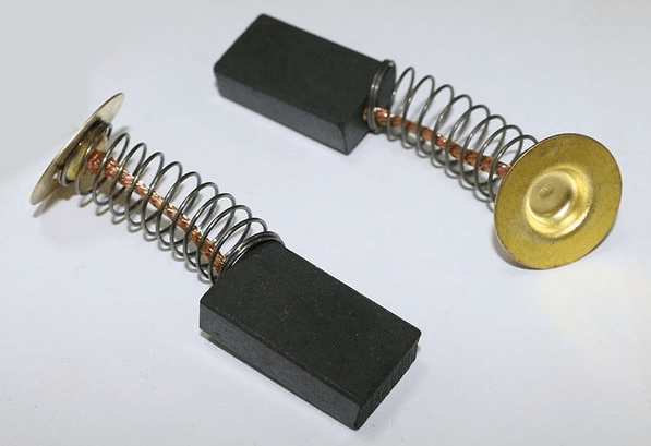 Extruded graphite motor brushes
 Another disadvantage of power tools is the frequent breakdown of the gearbox. This happens just because of the large starting torque. Dignity turns into disadvantage. With a breakdown of the gearbox, you have to change the tool, they are usually not subject to repair. Unfortunately, the industry, in an effort to reduce the cost of production, does this at the expense of quality. If you want to use a good power tool, pay a lot of money.
With the last drawback, it is just possible to effectively deal with a soft start. Many manufacturers do this, but do not always pay enough attention to it. Not all tools have good speed controllers.
Soft start - what is it for?
To reduce the unreasonable load on the mechanics of the power tool during start-up, measures can be taken on the part of the power supply. Instead of applying full voltage to the motor from the source (mains), you can apply reduced voltage using a soft start. But where to get it? It's about mass use. In some cases, specialists and craftsmen could solve this problem, but this was not available to most ordinary consumers.
There are three ways to limit the starting torque of a power tool and achieve a smooth start:
- The use of rheostats;
- Application of transformers;
- The use of semiconductor switches.
 The first method has been used for a very long time, but it is not economical and inconvenient.
It can be used on both direct and alternating current.
A significant part of the power is lost on heating the resistance of the rheostat. If the task is limited only to soft start, then this is quite tolerable. If in this way to regulate the operating speed of the electric motor, then this is an extra heating of the environment and energy consumption. In any case, the device is cumbersome.
The second way is much better and more economical. Suitable for AC only. It can also improve electrical safety when working with power tools. The downside is that classic transformers are now very expensive. Even with self-manufacturing, since they take a lot of expensive copper. The device is also quite large and heavy.
The third soft start method is the most modern and cheapest. It relies on the massive use of semiconductors. At one time, huge funds were invested in research and adjustment of the industrial production of semiconductor devices. But the cheapness of the materials from which they are produced, and the mass production have already managed to pay for everything. Due to their low cost, such devices are available to everyone.
The main feature of semiconductor switches is that there are no mechanical contacts and they operate at high speed (switching frequency). The currents switched by them can reach large values, at high voltages in the off state. At the same time, such devices practically do not heat up and do not consume excess energy, like rheostats and are great for modern power tools.
Types of semiconductor keys
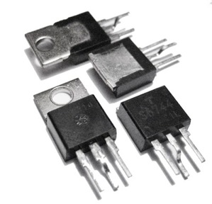 Thyristors and triacs
 The resistance of an open key reaches millions of ohms, the current through it practically does not flow.
The resistance of a closed key lies within units and tenths of an ohm.
Although a significant current may flow, too little voltage is dropped across the switch to generate much heat, according to the Joule-Lenz law. In both cases, it remains almost cold.
This applies to any of the types of power keys, of which there are three:
- Thyristors and triacs;
- MOSFET field effect transistors;
- IGBT transistors.
Historically, thyristors were the first to appear. With their help, the power in the alternating current circuits was regulated by controlling the unlocking phase of the device.

By adjusting the phase of the control voltage (duration t1), it is possible to influence the triggering moment of the triac in each half-cycle (t3) and, thus, the share of energy entering the load and, accordingly, the electric motor.
With the advent of powerful field-effect transistors with an insulated MOS gate (metal-oxide-semiconductor, or in English Metal-Oxide-Semiconductor Field Effect Transistor), the current in the circuit began to be controlled by changing the width of the opening pulses. This method is very effective in DC circuits, for which it is first rectified, and is used in welding inverters, frequency converters, etc.
For the most powerful power tools, IGBTs are used - insulated gate bipolar transistors. This is a combination of a field effect transistor with a bipolar one.
To regulate the electric motor, an already established, long-used solution based on triacs is currently used. More advanced solutions are not yet very common.
How to make a soft start yourself
Due to the simplicity of the circuit, it is not difficult to assemble a soft starter for an electric motor on a triac. It is made from readily available parts. It is best to do it on a printed circuit board, so nothing will hang out and close. The triac must be mounted on a heat sink made of aluminum. It is better if it is a factory radiator, designed for a power of 10-30 watts. Then it is suitable for a power tool with a power of 1000-1200 watts.
The calculation of the radiator is very simple to calculate by current. The triac drops about 1.5-2 volts of voltage when it is open. The current is obtained by dividing the power by the mains voltage. For example, a power tool with a rated power of 1200 W: 1200/220 = 5.45 amps. Multiply by 2, we get 11 watts.
Usually, in a commercial power tool, the power limiting circuit is hidden somewhere in the handle or body of the grinder or drill. There is no way to place a normal radiator. With frequent start-up, it overheats and does not perform its functions. Only a good professional power tool has a normal device for limiting starting torque and speed control.
NOTE: The power tool soft start module is best made in a socket box. Do not take too small socket boxes. It is difficult to place a normal radiator for a triac there. Without a radiator, the device will not be of practical use! When assembling the radiator with the device, it is necessary to ensure the cleanliness of the mating surfaces and a thin layer of heat-conducting paste (KTP-8 or an imported analogue).
The radiator must be mounted on the same board on which the rest of the parts are assembled. The board is placed in a box of suitable dimensions and strong enough. Such boxes can be bought in electrical goods or made from sheet plastic. A clean, empty jar of glue or paint with a screw-on or tight-fitting lid may work. It must be strong and unbreakable.
The socket installed in the device must be rated for the rated current of the motor used. A similar story with the network cord.
IMPORTANT! If the power tool is equipped with a speed control, its handle must be securely insulated. The device is under mains voltage and can be a source of electric shock if the insulation is poor.
After installation, it is useful to cover the printed circuit board with nitro-varnish to protect it from moisture. Schematic diagram and analysis of its operation in the next section.
Soft start on the KR1182PM1 chip
This is a microcircuit for Russian-made power tools, which is produced by NTC SIT CJSC (Bryansk). It can be purchased at retail in many online stores. Also the new name is K1182MP1R.
The microcircuit can be used without an external triac when the electric motor is operating at a load of up to 150 watts. This is too small for a power tool, but a more powerful triac can be used, which will increase the control power to 1-1.5 kW. A diagram using it is shown below:

Inside the chip is a control signal amplifier. This signal is generated at pins 3 and 6 of the microcircuit. The triggering phase of the triac is proportional to the voltage between pins 3 and 6, which can vary from 0 to 6 V. At zero, the load is off. When turned on, the capacitor actually short-circuits the control circuit. But it charges quite quickly and this forms a smooth overclocking.
Resistor R1 allows the capacitor C1 to discharge faster to reduce pauses between switching on. At full voltage, the load operates at close to nominal power. This voltage is created by the microcircuit itself, and the external circuit only “shorts” it in order to influence the triac turn-off phase in each half-cycle of the mains voltage.
Switch S1 can be used instead of a switch operating in the break of the network circuit. Only it works the other way around, when opened, the electric motor starts, and when closed, it turns off. The current in the circuit of this switch is very small and any microswitch can be used. However, there must be a way to quickly turn off the power tool anyway! That is, you can not do without an emergency power switch.
Using a variable resistor in place of R1 will allow you to more or less smoothly adjust the speed of the electric motor. Such a function, in addition to soft start, can be very useful when working with various materials that require their own processing speed.
Usually, the soft start time of the tool can be limited to 0.3 - 0.5 sec. This provides a significant increase in the service life of the device. If the power tool is powerful and resourceful, it can suddenly be pulled out of the hands of the worker with all the unpleasant consequences. In such cases, an even smoother start is needed. You can choose a suitable overclocking delay using the graph shown below:

This data was obtained in the ngspice program based on the characteristics taken from the manufacturer's documentation. In addition, they were tested in practice, with a 1500 W angle grinder and showed a good fit.
The VS1 triac can be taken as BT139-600 (Philips), TS106-10-6 (Russia, NWTP), BTB10-600BWRG (ST Microelectronics) or another similar one. Capacitors of the K50-35 type for an operating voltage of 50 V, with a capacity of 1 mF (C2.3) and 5-100 mF for C1. Resistor R2 type MLT-0.5. Also in the circuit it is desirable to use a fuse with a rated current that is 15-20% higher than the rated current of the intended load.
An example of installing a soft start motor on a grinder:
Embedded, based on KRRQD-12A (KRRQD-20A)
The author of this video gives an interesting example of how to make a built-in soft start of an electric motor using a universal extension cord KRRQD-12A (KRRQD-20A), for almost any power tool, up to 12A (20A) at a load. With a maximum power input of the tool up to 2500W(4400W).
other methods
Among other soft start methods for power tools, the use of transformers can be noted. For example, it will be a fairly versatile 1-1.5 kW LATR. Although this is a rather heavy device, it can help out if it is at hand, then you do not have to assemble another device.
Sometimes parallel sets of capacitors are used as "cold" resistance in an AC circuit, using their reactance at a frequency of 50 Hz:

Given the high operating voltage of the capacitors and their capacitance, the battery will be too large. This solution was sometimes applied before, but is now too outdated.
To limit the power in the load of the electric motor, a powerful diode can be used, with a reverse voltage of at least 250 V. It “cuts off” one half-cycle of the mains voltage, but this creates interference and uneven torque. Both of the latter methods, with capacitors and a diode, require switches to bypass the circuit. In the case of capacitors, quenching resistors will also be required to limit the short-circuit current of the capacitances.
In general, of all the soft start methods for power tools, the most inexpensive, reliable and convenient is to recognize the phase adjustment using the K1182MP1R microcircuit.
For everyone who has been using the grinder for more than one year, it broke. At first, each master tried to repair the sparkling grinder on his own, hoping that it would work after replacing the brushes. Usually, after such an attempt, a broken tool remains lying on a shelf with burned-out windings. And a new grinder is bought to replace it.
Drills, screwdrivers, rotary hammers, milling cutters are necessarily equipped with a speed dial regulator. Some so-called calibration grinders are also equipped with a regulator, and ordinary grinders have only a power button.
Manufacturers do not deliberately complicate low-power angle grinders with additional circuits, because such a power tool should be cheap. It is clear, of course, that the service life of an inexpensive tool is always shorter than that of a more expensive professional one.
The simplest angle grinder can be upgraded so that the gearbox and armature winding wires will no longer be damaged. These troubles mainly occur during a sharp, in other words, shock start of the grinder.
All modernization consists only in assembling the electronic circuit and fixing it in the box. In a separate box, because there is very little space in the handle of the grinder.
A tested, working circuit is laid out below. It was originally intended to adjust the incandescence of lamps, that is, to work on an active load. Her main asset? simplicity.
- The highlight of the soft starter, the schematic diagram of which you see, is the K1182PM1R chip. This microcircuit is highly specialized, of domestic production.
- The acceleration time can be increased by choosing a larger capacitor C3. While this capacitor is being charged, the electric motor speeds up to maximum.
- No need to replace the resistor R1 variable resistance. The 68 kΩ resistor is optimally matched for this circuit. With this setting, you can smoothly start the grinder with a power of 600 to 1500 watts.
- If you are going to assemble a power regulator, then you need to replace the resistor R1 with a variable resistance. A resistance of 100 kΩ or more does not lower the output voltage. By short-circuiting the legs of the microcircuit, you can completely turn off the connected angle grinder.
- By inserting a TS-122-25 semistor VS1 into the power circuit, that is, at 25A, you can smoothly start almost any grinder available for sale, with power from 600 to 2700 watts. And there is a large margin of power in case the grinder jams. To connect grinders with a power of up to 1500 W, imported seven-stores BT139, BT140 are enough. These less powerful electronic keys are cheaper.
The triac in the above circuit does not fully open, it cuts off about 15V of the mains voltage. Such a voltage drop does not affect the work of the grinder. But when the sevenstor is heated, the speed of the connected tool is greatly reduced. This problem is solved by installing a radiator.
This simple circuit has another drawback - its incompatibility with the speed controller installed in the tool.
The assembled circuit must be hidden in plastic boxes. The housing made of insulating material is important, because you need to protect yourself from mains voltage. You can buy a junction box at an electrical supply store.
A socket is screwed to the box and a cable with a plug is connected, which makes this design look like an extension cord.
If experience allows and there is a desire, you can assemble a more complex soft start circuit. The circuit diagram below is standard for the XS-12 module. This module is installed in the power tool at the factory.
If you need to change the speed of the connected electric motor, then the circuit becomes more complicated: a tuning resistor of 100 kOhm is installed, and a control resistor of 50 kOhm is installed. Or you can simply and roughly introduce a 470 kΩ variable between a 47 kΩ resistor and a diode.
In parallel with the capacitor C2, it is desirable to connect a resistor with a resistance of 1 MΩ (it is not shown in the diagram below).
The supply voltage of the LM358 chip is in the range from 5 to 35V. The voltage in the power circuit does not exceed 25V. Therefore, you can do without an additional zener diode DZ.
Whatever soft starter you build, never turn on the tool connected to it under load. Any soft start can be burned if you rush. Wait for the grinder to unwind, and then work.
Do-it-yourself washing machine repair Repair of transformers with welded cores. Do-it-yourself lithium-ion battery: how to properly charge


